
Constructing
a Parabola
By
Sharon K. O’Kelley
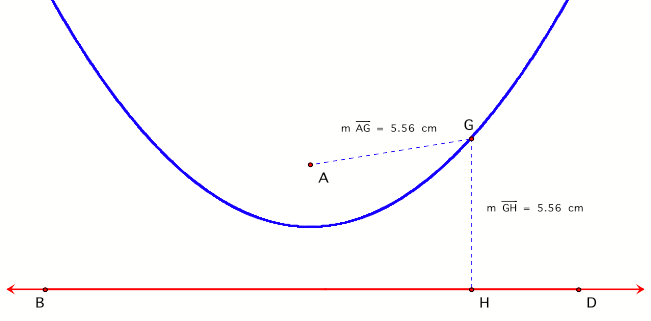
A parabola is defined
as the set of points equidistant from a line, called the directrix, and a fixed point, called the focus. In the diagram below, point A is the focus of the
parabola and line BD is the directrix. Note that point G on the parabola is
equidistant from both the focus and the directrix.
Constructing an
accurate parabola is difficult to do by hand. However, using Geometer’s Sketchpad
makes the task easier and enjoyable. It also can serve as an introduction to
Conics which is touched upon at the end of this investigation.
Step-by-Step
Construction of a Parabola
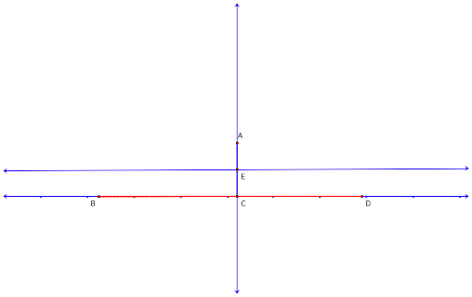
1. In figure 1, point A
is constructed as the focus and line BD as the directrix.
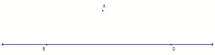
Figure
1
2. Next, point C is randomly constructed on segment BD. Through C, a line perpendicular to segment BD is constructed. Point C must be constructed randomly to insure that the perpendicular line can move along segment BD.
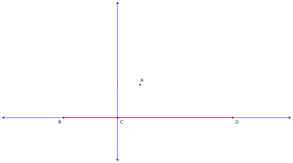
Figure
2
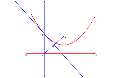
3. Now, segment AC is constructed with its
perpendicular bisector line FE.
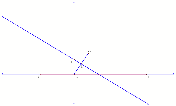
Figure
3
To understand this
step, it might be helpful to keep in mind the definition of the parabola and to
think about its vertex. Its vertex will be located at point E halfway between
line BD and point A when the perpendicular is in line with point A. (See figure
4.)
Figure
4
4. Next, select point F,
choose “trace” from the Display Menu and then drag point C back and forth along
segment BD to draw the parabola as shown in figure 5. (The more you “trace” the
parabola the darker it becomes.)
Figure
5
To
download a GSP animation of figure 5, go here and
select “Animate Point.”
5. Geometer’s Sketchpad allows for two alternate
constructions of parabolas as well.
a. The parabola in figure 6 has been created by
tracing the perpendicular line FE as point C is dragged along segment BD.
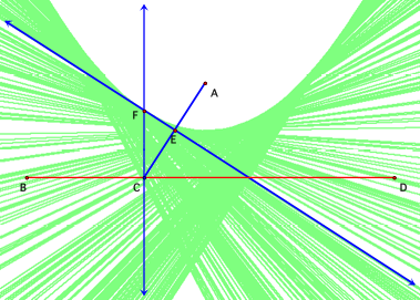
Figure 6
b.
The parabolas in figures 7 and 8 have been constructed using the locus command
in the Construct Menu. (Figure 7 uses points C and F and figure 8 uses point C
and line FE.) Note that this command yields the same results found above.
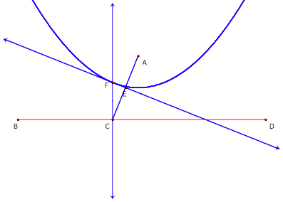
Figure 7
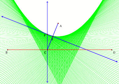
Figure 8
Connections to the other Conic Sections
6. What if the
directrix was a circle instead of a line?
a. Consider figure 9 when
point A is outside circle O and the line perpendicular to segment AB has been
selected to trace. When point B is moved around the circle, a hyperbola is
created.
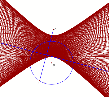
Figure 9
b. Now
consider figure 10 when point A is inside the circle. When point B is moved
around the circle, an ellipse is created.
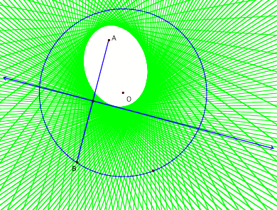
Figure 10