GEARS - Math in Context
by
Jackie Ruff
Once
set in motion by a power source, gears can transfer that motion to
another axis or another plane, speed things up, slow things down,
create changes in torque and generally control the rate of motion.
Sometimes gears are set up side by side to change a rate of rotation.
At other times they are placed within and on top of each other to
save space and to keep the same axis of rotation. Gears in this configuration are called planetary gears. An example of
this would be found inside an electric screwdriver. The motor turns a gear
surrounded by other gears that are fixed in a housing which is itself a
gear with the teeth on the inside. Here is a drawing of the
exploded view from a patent application for a screwdriver (Soreo, Schaub, & Levine, 2002).
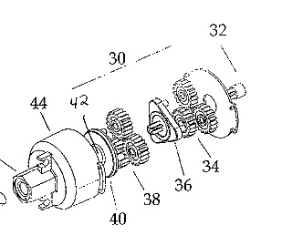
According to the description in this patent application, there are two sets of planetary gears, each reducing the rotations per minute of the electric motor shaft by 8:1 for a total reduction of about 64:1. By using this speed reduction ratio, 64 turns of the motor result in 1 turn of the chuck. This enables a relatively weak electric motor to spread the force required to turn a screw into wood over many turns.
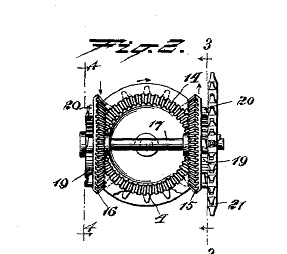
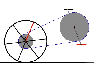
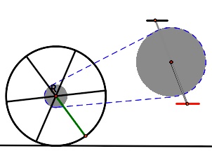
Conical gears, also called bevel gears, can move the axis of rotation to a perpendicular plane. According to the website, HowStuffWorks, an example of this would be a car differential which bends the rotation of the engine 90 degrees to drive the rear wheels. There is also an interesting example in Joseph Wheatley's design for a bicycle below (Wheatley, 1897).
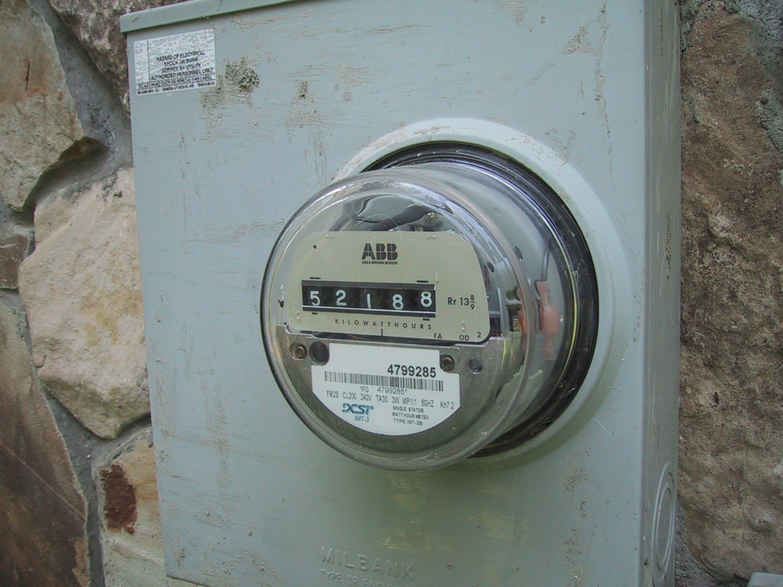
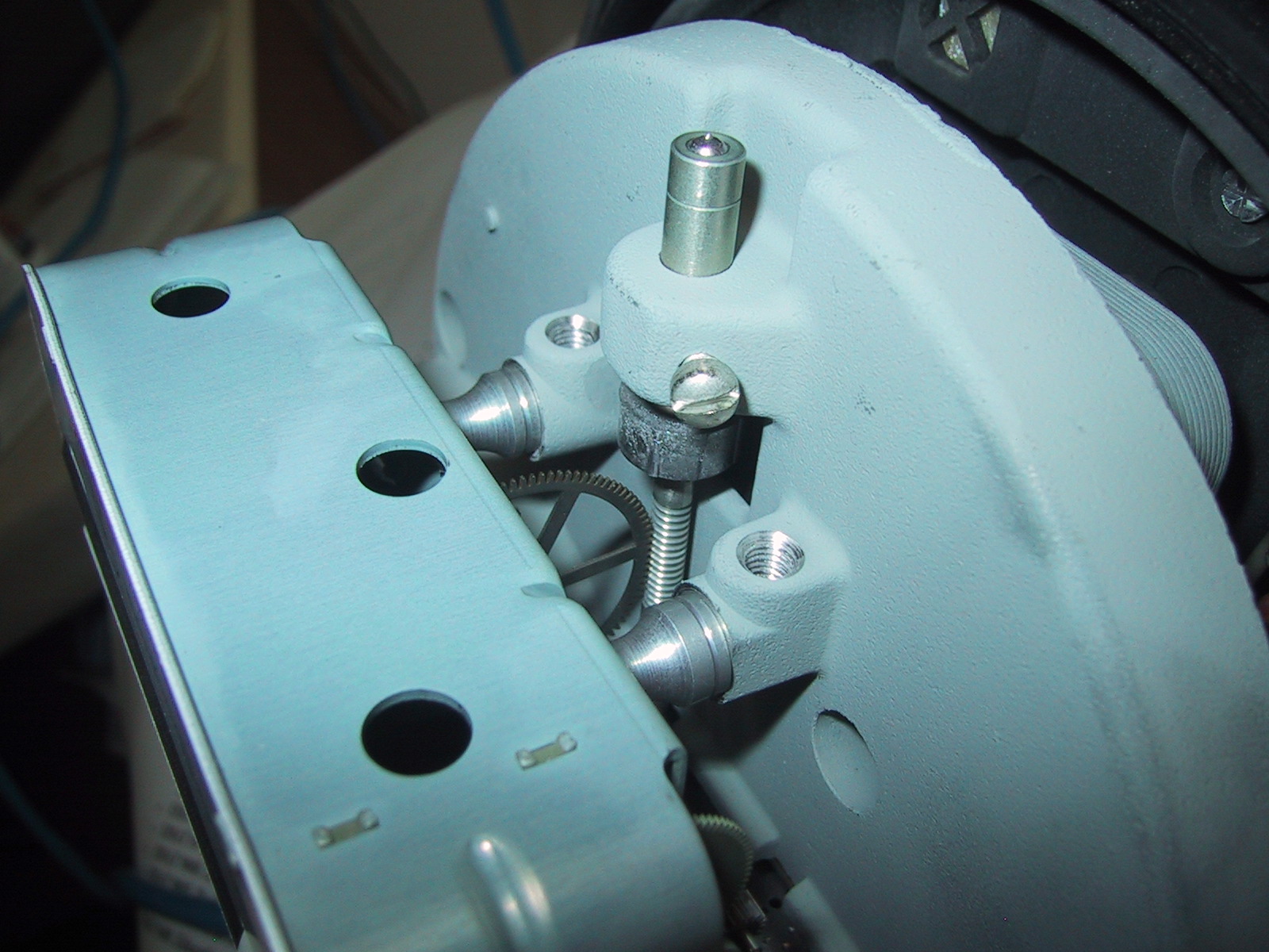
Another type of gear, called a worm gear, can be found in an electric meter, the type of meter found on the outside of a residence to measure electricity usage. A worm gear, which looks just like a threaded screw, transfers the spin of the disk in the meter to the pick-up gear as shown in the picture on the right below.
A
worm gear acts as a gear with one tooth. The pick-up gear has 100
teeth (in the model pictured here), so the ratio between these two
gears is 100:1. The motion is then transferred through a gear
train, pictured below, to the meter register which counts and displays
kilowatt hours of electricity used.
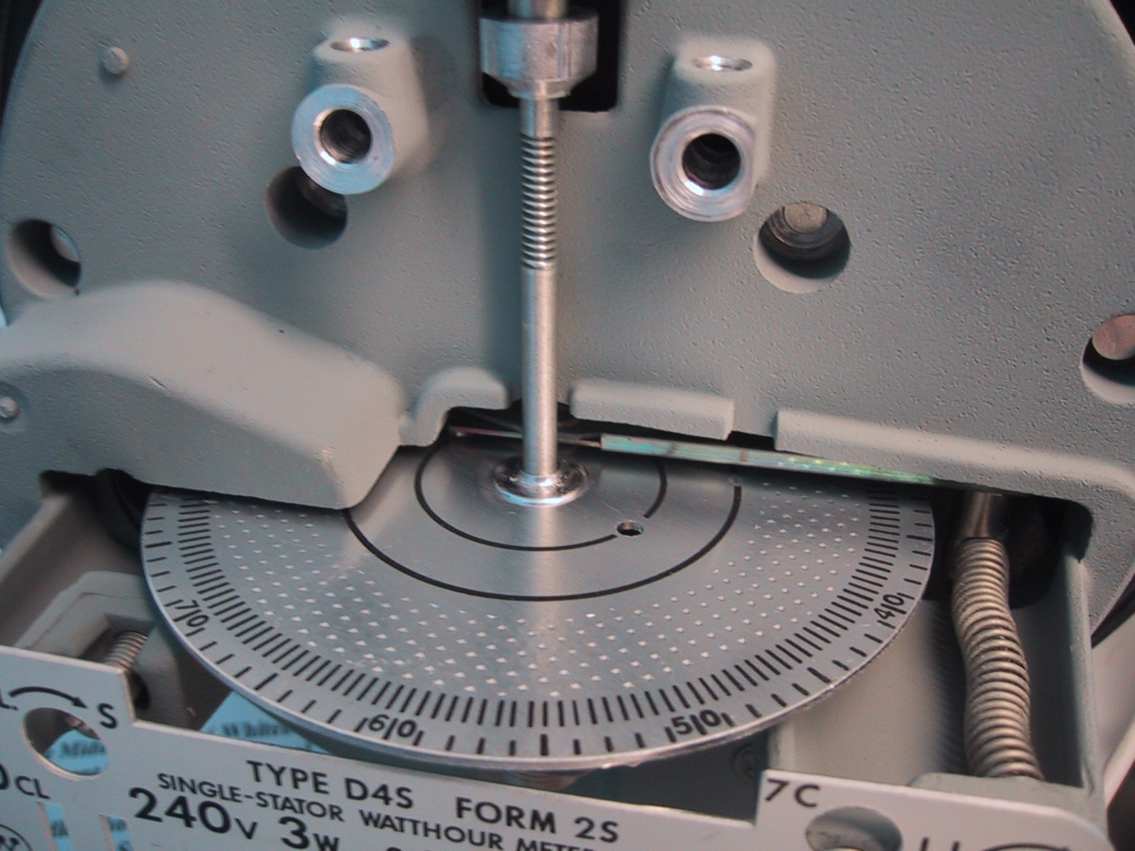
In fact, the number  is printed on the front of the meter as the Rr number (Megraw, Mumm, Roode, & Yockey, 2002), the number of
revolutions of the pick-up gear for a full revolution of the rightmost
dial (the view in the picture above is from the rear) . The only other
number on the meter, relative to the kilowatt register, is the Kh number. For this meter, Kh = 7.2. This number is the disk constant that defines the size of the particular meter.
is printed on the front of the meter as the Rr number (Megraw, Mumm, Roode, & Yockey, 2002), the number of
revolutions of the pick-up gear for a full revolution of the rightmost
dial (the view in the picture above is from the rear) . The only other
number on the meter, relative to the kilowatt register, is the Kh number. For this meter, Kh = 7.2. This number is the disk constant that defines the size of the particular meter.  Unfortunately
due to the minute size of the gears in this mechanism and the fact that
there are some weights inside the digit disks, this writer was not able
to completely resolve the ratios involved in this gear train.
Unfortunately
due to the minute size of the gears in this mechanism and the fact that
there are some weights inside the digit disks, this writer was not able
to completely resolve the ratios involved in this gear train.
The teeth on the gears of a bicycle are much easier to see and count. The ratios between the cogs
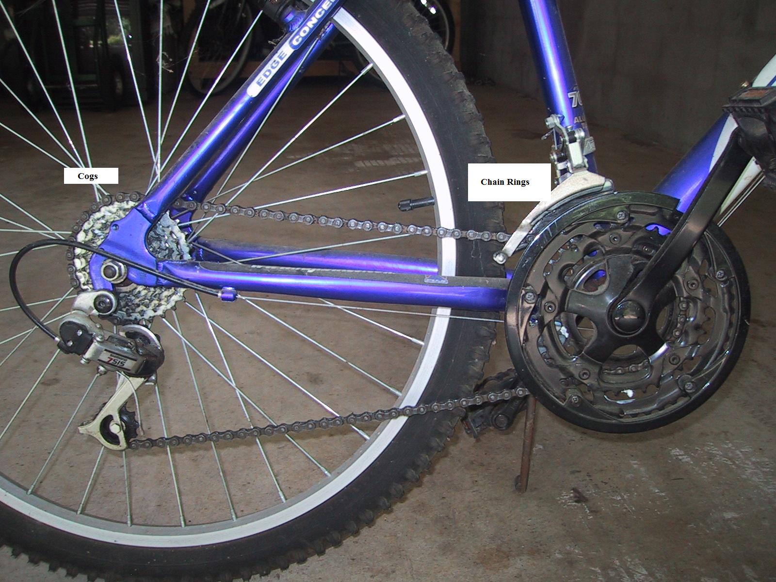
mounted on the rear wheel and the chain rings connected to
the pedals allow the rider to climb hills more easily
and increase speed on level paths. On the Fuji M-550AX bicycle, the number of teeth on the rear cogs are 13, 15, 17, 19, 21, 24, and 28 while the number of teeth on the chain rings are 28, 38, and 48. Since each cog can be linked to each chain ring, there are 7 times 3 or 21 possible gear ratios, giving us a 21 speed bike. If the 28 toothed cog is paired with the 28 toothed chain ring, each turn of the pedals gives us 1 turn of the rear wheel.
Before we go any further with the bicycle, we will look more closely at a gear ratio.
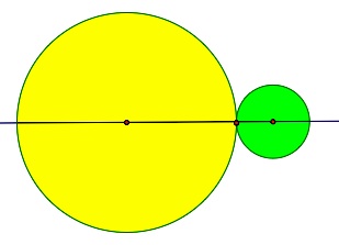
In the diagram at the left, the green gear has a diameter that is one third of the diameter of the yellow gear. That means that a tooth on the green gear would revolve three times as fast as a tooth on the yellow gear. If the yellow gear is driving the green gear and is attached to an axis turning at 100 rpm, then the axis to which the green gear is attached will revolve at 300 rpm. The rotational motion has been multiplied by a factor of 3. Here is a GSP file to see this rotation. The file also contains gears in the ratio of 10:1. This would be useful, as mentioned earlier in the electric meter discussion, to run a counter using base 10. Also in the sketchpad file are gears with the same axis of rotation in the ratio 60:1 making a clock with a second and minute hand.
We will also use a Geometer's Sketchpad file to explore the bicycle ratios before we go back to the real bike. In this file a bicycle has been constructed (rear wheel and pedals only) with two chain ring to cog ratios to choose. We should note that even though these two gears are connected by a chain, the chain locks 1 tooth of each gear into 1 section of the chain so the chain itself has no effect on the gear ratio. It serves only to give distance between the two axes of rotation. So, here are the bikes.
In this sketchpad demonstration, the bike on the left has a cog with radius x and a chain ring with radius 2x.
This gives a gear ratio of 2:1. But the ratio of the number
of revolutions is the inverse of the ratio of the radii, so Pedal
revolutions:Cog revolutions is 1:2. So, for each revolution of
the pedal, the rear wheel turns twice. The smaller the cog,
relative to the chain ring, the more distance one can cover for each
pedal turn. This gear combination multiplies your pedal
revolutions by 2 to give twice as many rear tire rotations.
The other bike has a cog with radius with the same chain ring, radius 2x.
The chain ring: cog ratio is 3:1. But the ratio of
revolutions, chain to cog, would be 1:3. The gear combination
multiplies your pedal revolutions by 3 to give the number of rear tire rotations.
The number of wheel revolutions is proportional to the number of
pedal turns with the gear ratio being the constant. Before returning to
the real bike and looking at some equations, the reader should open the
gsp file and watch the two bikes travel from the starting to finish
lines.
with the same chain ring, radius 2x.
The chain ring: cog ratio is 3:1. But the ratio of
revolutions, chain to cog, would be 1:3. The gear combination
multiplies your pedal revolutions by 3 to give the number of rear tire rotations.
The number of wheel revolutions is proportional to the number of
pedal turns with the gear ratio being the constant. Before returning to
the real bike and looking at some equations, the reader should open the
gsp file and watch the two bikes travel from the starting to finish
lines.
Here again are the possible chain ring to cog ratios for the Fuji bike.
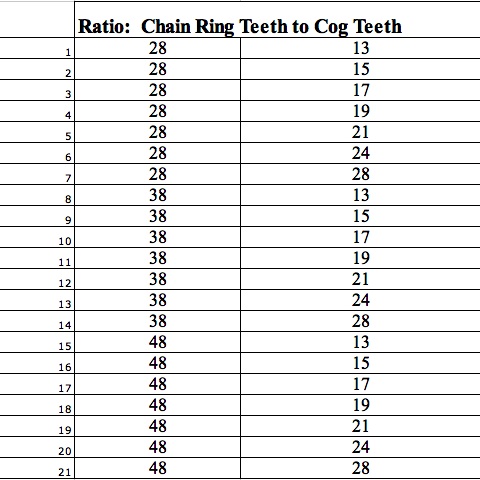
Next we will select a few gears and use the ratio to give us the number of wheel rotations that would result from several numbers of pedal turns. Then we will graph the results.
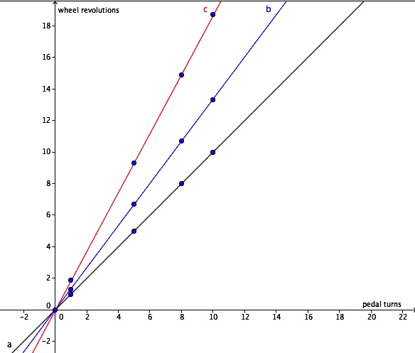
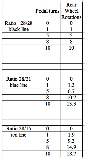
The graph illustrates the linear relationship and shows that the number of wheel revolutions is a function of the pedal turns with a slope of the gear ratio. An excellent lesson allowing students to investigate this linear relationship is outlined by Sheryl Stump in an article in The Mathematics Teacher (2000).
If the reader wants to know more or see some gears in action, try LEGO.
Thanks to the Upson E. M. C. for providing two kilowatt-hour meters.
Megraw, K., Mumm, D., Roode, M., Yockey, S. (2002). The Theories and Modeling of the Kilowatt-Hour Meter. Retrieved June 5,
2009 from http://www.korrekt.com/energy/watt_hour_power_meter/Physics222Project.pdf
Ryan, V. (2009). Gears and Pulleys. Retrieved June 3, 2009, from http://www.technologystudent.com/gears1/geardex1.htm
Soreo, R., Schaub, B., Levine, D. (2002). Battery powered screwdriver and screw starting device patent. Retrieved
June 8, 2009, from http://www.google.com/patents/about?id=CHoQAAAAEBAJ&dq=Patent+6776069
Stump, S. (2000). Doing mathematics with bicycle gear ratios. The Mathematics Teacher, 93(9), 762-765.
Wheatley, Joseph. (1897). Bicycle patent. Retrieved June 8, 2009, from
According to the description in this patent application, there are two sets of planetary gears, each reducing the rotations per minute of the electric motor shaft by 8:1 for a total reduction of about 64:1. By using this speed reduction ratio, 64 turns of the motor result in 1 turn of the chuck. This enables a relatively weak electric motor to spread the force required to turn a screw into wood over many turns.
Conical gears, also called bevel gears, can move the axis of rotation to a perpendicular plane. According to the website, HowStuffWorks, an example of this would be a car differential which bends the rotation of the engine 90 degrees to drive the rear wheels. There is also an interesting example in Joseph Wheatley's design for a bicycle below (Wheatley, 1897).
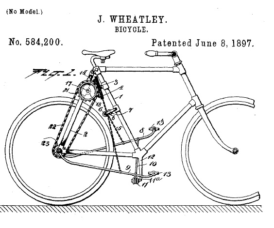 | The pedals seem to pump up and down. The motion of gear 3 is then transferred by bevel gears to the plane of the rear tire, propelling the bike. |
 |
Another type of gear, called a worm gear, can be found in an electric meter, the type of meter found on the outside of a residence to measure electricity usage. A worm gear, which looks just like a threaded screw, transfers the spin of the disk in the meter to the pick-up gear as shown in the picture on the right below.
 |  |
 |
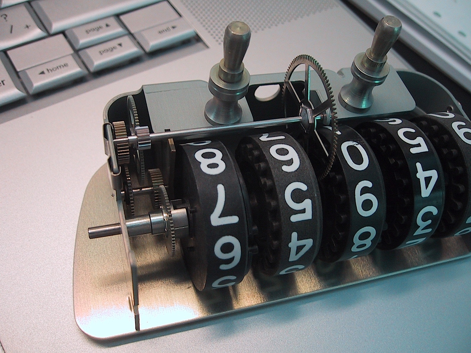 It seems that for every 100 rotations of the disk, the pick-up gear rotates once. When the pick-up gear is turned almost 14 times, the first dial of digits (the ones place) rotates completely, and the next dial (the tens place) rotates by 1 digit, registering 10 kilowatt hours. |
is printed on the front of the meter as the Rr number (Megraw, Mumm, Roode, & Yockey, 2002), the number of
revolutions of the pick-up gear for a full revolution of the rightmost
dial (the view in the picture above is from the rear) . The only other
number on the meter, relative to the kilowatt register, is the Kh number. For this meter, Kh = 7.2. This number is the disk constant that defines the size of the particular meter. Unfortunately
due to the minute size of the gears in this mechanism and the fact that
there are some weights inside the digit disks, this writer was not able
to completely resolve the ratios involved in this gear train.The teeth on the gears of a bicycle are much easier to see and count. The ratios between the cogs
mounted on the rear wheel and the chain rings connected to
the pedals allow the rider to climb hills more easily
and increase speed on level paths. On the Fuji M-550AX bicycle, the number of teeth on the rear cogs are 13, 15, 17, 19, 21, 24, and 28 while the number of teeth on the chain rings are 28, 38, and 48. Since each cog can be linked to each chain ring, there are 7 times 3 or 21 possible gear ratios, giving us a 21 speed bike. If the 28 toothed cog is paired with the 28 toothed chain ring, each turn of the pedals gives us 1 turn of the rear wheel.
| This was the case with
the old high wheel bicycles except that the pedals controlled the front
wheel. Since every pedal rotation resulted in one rotation of the large
wheel, these bicycles would have required forceful pedal strokes to move
forward, even on level ground. Looking again at the modern bike, if a chain ring is paired with a smaller cog wheel, the rear wheel turns more for each turn of the pedals. The rider then covers more distance for each turn. This would be good for increasing speed or for traveling along easy terrain. However, when traveling up an incline the rider can change the gear ratio so that for each turn of the pedals less distance is covered. This reduces the force required to turn the pedals since less work is accomplished with each turn. Using a larger cog wheel allows the force to be spread over a greater time making the pedaling more manageable. |  |
| highwheel bicycle photo http://en.wikipedia.org/wiki/File:Ordinary_bicycle01.jpg |
Before we go any further with the bicycle, we will look more closely at a gear ratio.
In the diagram at the left, the green gear has a diameter that is one third of the diameter of the yellow gear. That means that a tooth on the green gear would revolve three times as fast as a tooth on the yellow gear. If the yellow gear is driving the green gear and is attached to an axis turning at 100 rpm, then the axis to which the green gear is attached will revolve at 300 rpm. The rotational motion has been multiplied by a factor of 3. Here is a GSP file to see this rotation. The file also contains gears in the ratio of 10:1. This would be useful, as mentioned earlier in the electric meter discussion, to run a counter using base 10. Also in the sketchpad file are gears with the same axis of rotation in the ratio 60:1 making a clock with a second and minute hand.
We will also use a Geometer's Sketchpad file to explore the bicycle ratios before we go back to the real bike. In this file a bicycle has been constructed (rear wheel and pedals only) with two chain ring to cog ratios to choose. We should note that even though these two gears are connected by a chain, the chain locks 1 tooth of each gear into 1 section of the chain so the chain itself has no effect on the gear ratio. It serves only to give distance between the two axes of rotation. So, here are the bikes.
 |  |
The other bike has a cog with radius
with the same chain ring, radius 2x.
The chain ring: cog ratio is 3:1. But the ratio of
revolutions, chain to cog, would be 1:3. The gear combination
multiplies your pedal revolutions by 3 to give the number of rear tire rotations.
The number of wheel revolutions is proportional to the number of
pedal turns with the gear ratio being the constant. Before returning to
the real bike and looking at some equations, the reader should open the
gsp file and watch the two bikes travel from the starting to finish
lines.Here again are the possible chain ring to cog ratios for the Fuji bike.
Next we will select a few gears and use the ratio to give us the number of wheel rotations that would result from several numbers of pedal turns. Then we will graph the results.
The graph illustrates the linear relationship and shows that the number of wheel revolutions is a function of the pedal turns with a slope of the gear ratio. An excellent lesson allowing students to investigate this linear relationship is outlined by Sheryl Stump in an article in The Mathematics Teacher (2000).
If the reader wants to know more or see some gears in action, try LEGO.
Thanks to the Upson E. M. C. for providing two kilowatt-hour meters.
References:
Megraw, K., Mumm, D., Roode, M., Yockey, S. (2002). The Theories and Modeling of the Kilowatt-Hour Meter. Retrieved June 5,
2009 from http://www.korrekt.com/energy/watt_hour_power_meter/Physics222Project.pdf
Ryan, V. (2009). Gears and Pulleys. Retrieved June 3, 2009, from http://www.technologystudent.com/gears1/geardex1.htm
Soreo, R., Schaub, B., Levine, D. (2002). Battery powered screwdriver and screw starting device patent. Retrieved
June 8, 2009, from http://www.google.com/patents/about?id=CHoQAAAAEBAJ&dq=Patent+6776069
Stump, S. (2000). Doing mathematics with bicycle gear ratios. The Mathematics Teacher, 93(9), 762-765.
Wheatley, Joseph. (1897). Bicycle patent. Retrieved June 8, 2009, from
http://www.google.com/patents?hl=en&lr=&vid=USPAT584200&id=U0ddAAAAEBAJ&oi=fnd&dq=Patent+584200+Joseph+Wheatley