

A topic that is never treated in high school geometry (or physics)
is that of mechanical linkages or mechanisms. The topic is actually
one of mechanical engineering, but provides a rich field for geometric
exploration. A dynamic geometry software package such as Geometer's
Sketchpad can be used to create and explore the possibilities
and limitations of many mechanical devices.
It is easy to believe that the "electronic age" has
surplanted the need for mechanical devices, but consider:
the sliding tray on your computer's CD drive opens by mechanical means, your printer, copy machine, fax, or scanner are full of gears and linkages, the steering and suspension on your car has changed very little since its conception, linkages operate sewing machines, shutters on film cameras, piano keyboards, construction machinery, and the parking lot arms that keep most of us out of the Aderhold parking lot.
This page demonstrates some linkages used to produce straight-line motion. In general, proofs are not provided. These explorations were mainly used to try and develop some expertise in using Geometer's Sketchpad, however, some mathematical investigations are included. A list of references is provided.
Watt's straight line linkage.
Lent (1961) states that
"Guiding a point along a straight line presents very few problems today, since it is a simple matter to produce very accurate plane surfaces along which a member may slide. Before James Watt could build his steam engine, he had to design a linkage to guide a pin along a straight line path, since there were no machine tools in 1769 capable of producing straight metal slides of sufficient precision." (p 15)
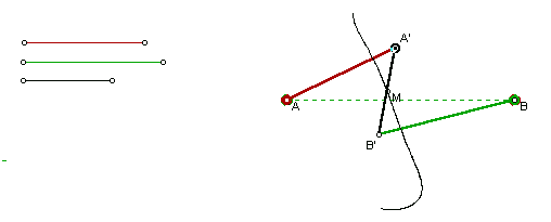
As an interesting side note, if A'B' = AB and AA' = BB' = AB/root 2, point M traces out a Lemniscate of Bernoulli as shown below.
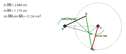
There are several possible configurations of Watt's linkages
as shown here.
None of them overcome the limitation of
GSP, but by reflecting some of the objects in the linkage, you
can "trick" GSP into drawing only the lemniscate.
Click here to see my solution.
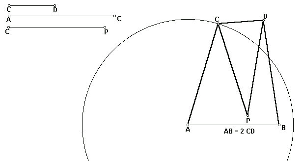
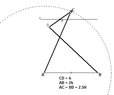
Peaucellier's Linkage (1867).
This was the first linkage proved to draw a true straight
line throughtout its range of motion.
Click the figure to open GSP and see the animation of this linkage.
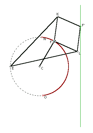
The epicyclic straight line mechanism.
While not based on linkages, a line segment is produced by this
device. A circle rolls around the inside of a second circle twice
the diameter of the first. A point on the smaller circle traces
out the diameter of the larger circle. Click here
to see a GSP sketch and animation of this mechanism.
Using dynamic geometry software to reproduce mechanical devices or to recreate classical methods for drawing common mathematical curves is a rich area for exploration. For example, how do you use geometry to draw a limaçon? Click here to see one way.
The books referenced below are from the University of
Georgia library, however much of the same information is available
on the World Wide Web.
Dijksman, E. A. (1976). Motion geometry of mechanisms. London: Cambridge University Press.
Huckert, J. (1958). Analytical kenematics of plane motion mechanisms. New York: The Macmillan Company.
Hunt, K. H. (1978). Kinematic geometry of mechanisms. Oxford: Clarendon Press.
Lent, D. (1961). Analysis and design of mechanisms. (p 15). Engelwood Cliffs, NJ: Prentice-Hall, Inc.
McCarthy, J. M. (2000). Geometric design of linkages. New York: Springer.
Schwamb, P., Merrill, A. L., James, W. H. (1948). Elements of Mechanism. (Rev. ed.). New York: John Wiley and Sons, Inc.
Weisstein, E. W. (2001). Eric Weisstein's world of mathematics.
Retrieved December 22, 2001 from
http://mathworld.wolfram.com/.
Wells, D. (1991). The Penguin dictionary of curious and interesting geometry. London: Penguin Books.
Return to D. Hembree's EMAT 6680 page
Email to: dhembree@coe.uga.edu