Elliptical Gears
When I was in
eight grades my first job was working on a conveyer belt at a metal and steel
factory. I never asked why the boxes would slide slowly while we were placing the
steel scraps in them and then speed up after they were full. I suppose that I
thought some guy was watching the belt and keeping the speed irregular so that
we could work more efficiently, but that would cost the factory extra money and
the efficiency of the man watching the belt would not be very high. He may be
more suited and more useful if he was cutting the steel or shaping the steel. Almost
anything that he could do would have been better than sitting on a stool
keeping the conveyer belt speed increasing and decreasing as the product moved
along the line.
After I
started my Masters Degree I finally understood how that belt worked. It had to
do with elliptical gears and the way they interact with each other that creates
the varying speed. It’s fairly simple to understand if you’ve already read
through the explanation of the ellipse in space, but the speed of an object
traveling around an ellipse increases as it gets closer to the major axis (or
the most extreme bend in the curve). Here’s a picture of two elliptical gears
interacting that I created on GSP.
And here’s a link to these same gears that you can experiment
with and watch the speed increase and decrease. Elliptical
Gears
And here are the rules/directions to the construction of
these two objects. It took me quite a while to come up with this, and there may
be a quicker way to do it. If you find a quicker and more elegant way to do
this then please do hesitate to email me at davidkdrew@yahoo.com.
Elliptical Gears
Construction on Geometer’s Sketchpad
The following steps are a construction of how and hopefully why two gears that are congruent ellipses rotate and stay together. The idea behind the elliptical gears was created by a need to have an inconsistent gear speed. Such devices are used in wood and stone cutting. Anyway, here are the construction directions.
- Open GSP and start by placing a point anywhere on the plane, and label it point A. Construct two circles of variable size both with center A.
- On the smaller circle place a point B on the edge of the circle, and on the larger circle place a point D on the edge.
- Construct segments, in a thick line, AB and AD, and hide everything except points A, B, D, and those two segments.
- Make a dashed segment through B and D. Find the midpoint and call it M1. Make a perpendicular through M1 with segment BD.
- Construct a line through A and D and call the intersection of that line with the perpendicular line I.
- Select D and I in that order and select locus under the construct tab. It’s nicer to make the ellipse a solid thick line but not necessary.
- To avoid confusion let’s hide the lines, not the segments, that we’ve just made. And hide M1 as well.
- The trick is to make another ellipse congruent to the one that we’ve just created as well as lining up the intersection point. We can start by saying that point D is one of the foci of the second ellipse and the point I is where they will meet and stay together as the rotation occurs.
- Start by making a circle with center D and radius equal to segment AB. Next make a circle with center B and radius AD. Finally select points B and I in that order and construct a ray.
- The ray and the two circles all intersect at one point we’ll call C. Select the big circle and the ray and find their intersection. Now hide all that we’ve just created except for point C.
- Make a circle with center D and radius AD. Construct point E on the edge of the circle.
- Make segment CE and find the midpoint N. Make a perpendicular with CE through point N.
- Make a line through D and E and call the intersection with that line and the perpendicular from 12 point I2.
- Make a line through I2 and C.
- Select E and I2 in that order and select a locus again under construct. This will bring up another ellipse exactly congruent to the first one.
- Now hide everything except points A, B, C, D and I and the two ellipses.
- Select point B, go under Edit and choose Action Buttons, then go to Animation and create an animation of point B.
- Watch the point I go back and forth in non-constant speed.
The last part
of this presentation on conic sections and the ellipse is a quick investigation
into bicycle cranks and gears. If you’ve ever ridden a bike enough to have to
wash it you may discover something interesting. Last year, while I was cleaning
my road bike I discovered that the front crank was wearing down or so it seemed.
For those of you that don’t know the front crank is the big set of cranks
closest to the handle bars. A road bike usually has two different cogs on the
front crank with a certain number of teeth that grab the chain and propel the
bike forward. There is also a front gear shifter that pulls the chain off one
cog and moves it to the other cog depending if you want a harder or easier
gear. As I was cleaning my chain and gear
cranks I discovered that the teeth on both the front cogs looked worn down so I
took my bike up to Atlanta Cycle and asked them what the deal was. One of the
mechanics blew my mind when he told me that nothing was wrong with my bike
because it was built like that. He started throwing around some bike
terminology that was boring a long winded but he did mention the word ellipse.
He said that the front two cranks were built in an elliptical shape by the
manufacturer, in the case of my bike it was the company Lemond Bicycles.
Since I didn’t
receive a full explanation of why the crank was elliptical I tried to make up
my own answer. I came up with the theory that the gears were elliptical so that
the power of your legs would be distributed more evenly through a regular pedal
revolution. I thought that your leg power is weakest at the top a bottom of a
pedal stroke so those places should be easier to turn over. It turns out that I
was wrong, and according to another mechanic at Atlanta Cycling it all has to do
with shifting gears.
Here’s a
diagram on GSP to show more detail of what I’m talking about.
The front
crank gets power from your legs and distributes it to the rear crank which
turns the back wheel to propel the bike. Sorry for the terrible drawing, but it’s
the best I could do with GSP. So back to the reason the front crank is
elliptical: it’s shaped like that because of the gear shifters.
Here’s a
picture of my bike on the right and on the left is a close up of the front cogs
and the shifting component.
|
|
|
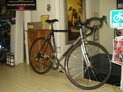
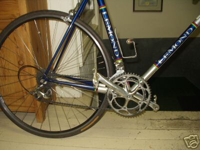
The picture on
the right is called the front bracket. It consists of two cogs, pedals, a
crank, some cable, and what is called a derailleur. The derailleur is the key
and the reason for the elliptical design. When you shift from one gear to the
next you may know that sometimes it takes longer to get into gear than other
times. The reason is that the elliptical design helps the chain slide off the
cog easier at a special point. And this special point is none other than the perigee
for the crank and the right pedal.
It makes
perfect sense if you think about it for a minute. Let’s suppose that the crank
were circular then the amount of force would be fairly strong in order to get
the chain off a particular cog. But if the cogs had a weak point such as where
the perigee is then the force would dramatically decrease. The perigee is the
weak point because it is moving at a slightly faster speed than the back cogs
so there is a small amount of time or a small margin of error that you could
slow the front cog while not reducing the speed of the rear cogs. Therefore you
can shift gears and slow the rotation of your legs for just a moment and not
reduce the speed your bike is carrying you.
Therefore we
now know why the front cog of many road bikes is slightly elliptical.