The
Centroid of the Quadrilateral
by
Mike Patterson
Uses of the Centroid in the Physical
World
"The term centroid is of recent coinage. It is used as
a substitute for the older term "center of gravity." (MT Jan 1960) The
properties of the centroid show up in a number of different disciplines
and research areas such as: location searches,
the sound spectrum and shape
properties.
The common investigation concerning the centroid for
middle school students is the triangle. We will change the focus to the
quadrilateral for this essay. Although our focus is the quadrilateral,
the patterns and ideas found within the triangle extend naturally to the
quadrilateral. The first place that this shows up is in its construction.
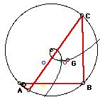
| Construction
of the Centroid of a Quadrilateral
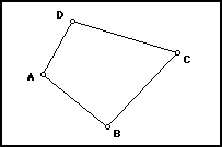
Any quadrilateral can be divided into two triangles by
drawing one of the diagonals. Find the centroids of these two triangles
and then connect the line segment between them. Create two new triangles
in the quadrilateral by drawing the other diagonal. Find the centroids
of these two triangles and then connect the line segment between them.
The two line segments of the four centroids intersect at G, the centroid
of the quadrilateral, as shown in the animation. |
 |
| Control
Factor - Cyclic Quadrilaterals
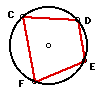
Cyclic Quadrilaterals are the group of quadrilaterals
where all four vertices are inscribed on a circle. It is also true of this
type of quadrilateral that the sum of opposite angles total 180 degrees.
By using a particular subgroup of the quadrilateral, I hope to find patterns
that I can extend to all quadrilaterals. |
 |
Follow the Centroid
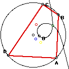
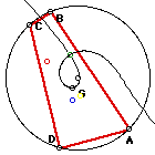
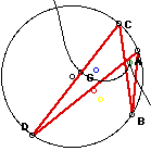
In the below diagrams I have traced the four centroids
of the triangles in the quadrilateral in red, blue, green and yellow. The
black trace is the centroid(G) of the quadrilateral.
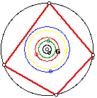
Method #1 - Holding the distance between the vertices
constant and studying the locus of the centroids of the triangles in the
quadrilateral and the centroid of the quadrilateral.
When the distances between the vertices is held fixed
the quadrilateral remains unaltered. It is simply rotated around the center
point of the circle with which it is inscribed. The pattern generated is
a series of concentric circles. This is of no surprise by nature of the
motion in which we move the shape, but what is of interest is the order
and size relationship of the circles. The black circle (G - centroid of
the quadrilateral) is quite variable.
 |
 |
 |
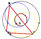
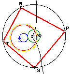
SHAPE #1 - similar angle size
Here the centroid(G) of the quadrilateral creates a circular path tight
to the center of the circle. The color pattern from largest to smallest
is blue, yellow, red, green, and black(G). Does this pattern hold for all
cyclic quadrilaterals?......nope! |
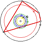
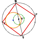
SHAPE #2 - one large angle
By altering the quadrilateral we see that it dramatically changes the
relationship of the paths of the centroids. Notice that the red centroid
is distant from the others. This is because of the large obtuse angle.
The path pattern here is red, green, blue, black(G) and yellow. |
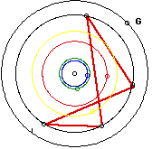
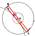
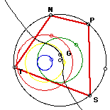
SHAPE #3 - concave
By altering the quadrilateral again we see that it dramatrically changes
the relationship of the paths of the centroids. The path pattern here is
black(G), yellow, red, green, and blue. In this particular case the centroid(G)
is outside the circle. |
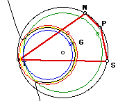
We do notice that the size of angles of the 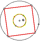 quadrilateral
directly affect the size and order of the circles formed by tracing the
centroids. If the quadrilateral was a square (diagram on the right) we
see four equal circles and that the centroid of the quadrilateral(G) would
be the center of the original circle. quadrilateral
directly affect the size and order of the circles formed by tracing the
centroids. If the quadrilateral was a square (diagram on the right) we
see four equal circles and that the centroid of the quadrilateral(G) would
be the center of the original circle.
As we alter the angles of the quadrilateral we would see that large
obtuse angles spread the circles out as in SHAPE #2 above. While
if the angles of the quadrilateral are quite close in size we would see
a clustering as in SHAPE #1. Finally, when we alter the shape dramatically
as in SHAPE #3, we find that it is possible to have the centroid
of the quadrilateral be outside of the quadrilateral. |
Method #2 - Holding the distance between three vertices
constant and while moving the fourth one along the circumcircle.
In this section we will follow the traced path of the
centroid(G) of the quadrilateral. It will become quite obvious that the
path does and can extend outside of the quadrilateral. This phenomenon
occurs as the quadrilateral folds onto itself creating a concave quadrilateral.
In the below diagrams we are moving point D while holding C, B and A constant.
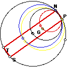
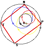
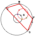
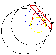
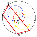
Method #3 - Holding the distance between two vertices
constant and while moving a fixed distance between the other two vertices.
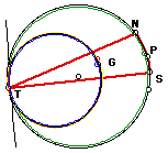
To explain which points are moving and their relationship
I will refer the first diagram below. For this method NP will be a fixed
unmoving point, while TS a fixed length will be moving.
|
NP a fixed small length
|
 |
 |
 |
SHAPE #1 - Two fixed equal lengths
(NP = TS)
Symmetry appears as we manipulate the two fixed equal lengths. With
some further investigation I am led to believe that the perpendicular bisector
of NP would form the axis of symmetry. (Look below for a similar example) |
SHAPE #2 - Length ST = Diameter
Symmetry once again becomes evident, while also generating only two
circles. Thus some of the centroids are following a identical path. (Look
below for a similar example) |
SHAPE #3 - TNP and SPN are large obtuse angles
I saw no particular new pattern or important information through this
example. |
|
NP a fixed larger length but smaller that the diameter
|
 |
 |
 |
SHAPE #4 - Two fixed equal lengths (NP =
TS)
The change in NP did not effect the symmetry. It changed the relationship
between the circle but the symmetry to the perpendicular bisector of NP
still held. |
SHAPE #5 - Length ST = Diameter
Two circles were formed again. We also notice in the larger model that
the Centroid of the quadrilateral goes through two centroids. |
SHAPE #6 - TNP and SPN are large obtuse angles
Again, I saw no particular new pattern or important information through
this example other than the size of the path of the centroid(G) extending
outside the circle. |
|
NP a fixed length equal to the diameter
|
 |
 |
 |
SHAPE #7 - TS is a very small length
As T and S approach the same point we see the centroids create tangents
to each other. If T and S became the same point we would have a right triangle,
and its centroid path would be a circle centered to the original circle's
center. |
SHAPE #8 - TS is larger but less than the diameter
The path of G falls exactly on the path of one of the other centroids.
The paths seem to hold symmetry though the perpendicular bisector of NP. |
SHAPE #9 - TS is very close to the length of the diameter
The path of G falls extends well beyond the boundaries of the original
circle, while still hold it symmetry to the perpendicular bisector of NP. |
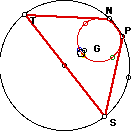
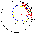
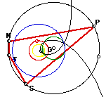
Method #4 - Holding a single point fixed while moving
three fixed points that preserve the distance between them.
To explain which points are moving and their relationship
I will refer the first diagram below. For this method the point T will
remain fixed while angle NPS moves around the circle.
 |
 |
 |
SHAPE #1 - Angle NPS is acute
From above I have begun to see that the size of the angles of the quadrilateral
make the most impact on the path of the centroid. Here we see a loop form
when the quadrilateral degenerates. |
SHAPE #2 - Angle NPS is just less than 90 degrees
We see the loop has reduced down, and the path is straightening. |
SHAPE #3 - Angle NPS is a right angle.
The path of G straightens out to become a line through the center of
the circle. |
 |
 |
 |
SHAPE #4 - Angle NPS is obtuse
From above |
SHAPE #5 - Angle NPS is s larger obtuse.
The larger the angle alters the path of the centroid such that a horseshoe
like shape is formed |
SHAPE #6 - Angle NPS is very close
to being straight
As angle NPS approaches 180 degrees see the paths of the centroids
all becoming a single circle. The line extending outside of the circle
is the portion the centroids path while the quadrilateral is degenerate. |
Summary: Many hours of investigating using the
"what if" approach helped me to find many interesting patterns concerning
the centroid. These patterns better focus my approach but they didn't seem
to reveal any startling or special relationships. This felt much like the
true method of discovery where one pursues numerous paths in hopes to make
that break through, not ever really knowing how far it is until the break
through is made. Thus far I don't feel that I have exhausted all the possibilities,
nor have I written up all that I have done....... This exploration will
continue......
The end for now